Industrial fan | Smart fan Overall solution service provider

Industrial fan | Smart fan Overall solution service provider


 13806436798
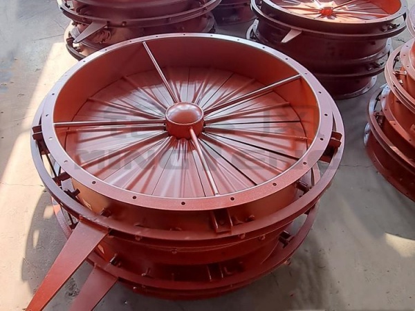
The fan inlet damper (also known as the inlet regulating damper or inlet baffle door) is installed on the fan inlet duct to adjust the cross-sectional area of the inlet airflow, controlling the inlet
01On site installation and debugging of equipment
02Regular follow-up visits
The fan inlet damper (also known as the inlet regulating damper or inlet baffle door) is installed on the fan inlet duct to adjust the cross-sectional area of the inlet airflow, controlling the inlet flow rate and air pressure of the fan. It is a traditional air volume regulating component for centrifugal induced draft fans and dust removal fans, often used either as an alternative to or in conjunction with a frequency converter.
1. Core role
1. Adjusting air volume and pressure: By rotating the louver baffle to change the inlet flow area, the gas flow entering the fan can be controlled, adapting to different working conditions and air volume requirements.
2. Shutdown and Cutoff: When the fan is shut down, the air door should be completely closed to block the airflow, reducing air reversals and cold air inflows in the pipeline after shutdown, thus protecting the impeller and dust removal equipment.
3. Reduce starting load: Close the air regulating valve before starting the fan to reduce the air intake during startup, lower the motor starting current, and mitigate the starting impact.
Distinction: The inlet air regulating valve is located on the inlet side of the fan; the outlet air valve has greater resistance and higher energy consumption, so the inlet air regulating valve is preferred for industrial induced draft fans.
II. Mainstream Types
1. Manual inlet air damper: Handwheel + connecting rod, manually rotated and adjusted on site. Low cost, simple structure; unable to be remotely and automatically controlled. 👉 Suitable for small fans with stable operating conditions and no need for frequent air volume adjustment.
2. Electric inlet air valve (most commonly used in industry) driven by electric actuator, 4-20mA signal, remote adjustment via central control, automatic closed-loop control. 👉 Dedusting, kiln induced draft, exhaust gas system, compatible with PLC.
3. Pneumatic inlet air regulating valve, driven by a cylinder, featuring fast response speed, is preferred in explosion-proof environments. 👉 Chemical and explosion-proof workshops with sufficient air supply conditions.
III. Structural composition
Valve body shell + multiple sets of louver adjustment blades + linkage transmission mechanism + actuator (manual/electric/pneumatic) + sealing sheet (optional: sealing packing, limit switch), reducing air leakage when closed.
IV. Material
Q235 carbon steel: room temperature air, ordinary dust removal flue gas, highest cost-effectiveness
304 stainless steel: humid, weakly corrosive flue gas
Wear-resistant steel plate: high dust erosion conditions
High-temperature materials: high-temperature flue gas, high-temperature resistant steel plates + high-temperature resistant seals
V. Key parameters for model selection
1. Pipe diameter and flange size
2. Medium temperature, dust content, and presence of corrosivity
3. Operating negative pressure (inlet is under negative pressure condition)
4. Drive mode: manual / electric / pneumatic
5. Is it necessary to implement a sealed shut-off (with zero leakage requirements)
6. Control signal: 4-20mA analog quantity (for automatic adjustment)
VI. Installation Key Points
1. Install it at the straight pipe section at the front end of the fan inlet, ensuring sufficient straight pipe distance before and after to avoid vortex flow and ensure adjustment accuracy.
2. The airflow direction cannot be installed reversely, and the airflow arrow is marked on the housing.
3. Reserve maintenance space for the linkage mechanism to prevent jamming.
4. Regularly clean the ash deposits on the blades under dusty working conditions, as ash buildup can cause the blades to become stuck and malfunction.
5. Pay attention to the sealing under negative pressure conditions to prevent external air infiltration after closure, which may cause falsely high air volume readings.
VII. Comparison of Advantages and Disadvantages
Advantages: Low one-time investment; capable of achieving complete shutoff and isolating airflow; simple maintenance and repair.
Disadvantages: Relying on throttling to maintain pressure will result in resistance loss and high energy consumption; prolonged operation at a small opening is prone to increased vortex, vibration, and noise.
VIII. Common faults
1. Blade jamming: dust accumulation, rusted connecting rod, actuator alarm
2. Large air leakage: worn sealing strips, poor closure, and wild air entering the system
3. Regulation failure: connecting rod pin detachment, actuator malfunction
4. Vibration noise: small-scale airflow vortex induces shell resonance
You can also contact us for more models and support customization

You only need one phone call
Leave the rest to us

The sales team will have a detailed discussion with you
Tell us your needs

Engineers based on your requirements
Provide a reasonable solution for the demand

We will do it within a reasonable time frame
Complete with quality and quantity assurance

Installation team on-site installation
Debugging until stable production

Any problems in the later stage are welcome
Contact the after-sales engineer
You can also contact us for more models and support customization
You only need one phone call. Leave the rest to us
The sales team will have a detailed discussion with you and tell us your needs
Engineers provide reasonable solutions based on your needs
We will complete it with high quality and quantity within a reasonable time
Installation team on-site installation, debugging until stable production
If there are any problems in the later stage, you can contact the after-sales engineer
 13806436798
Mobile