Industrial fan | Smart fan Overall solution service provider

Industrial fan | Smart fan Overall solution service provider


 13806436798
Centrifugal fans are the most common type of "pressurized air supply and exhaust" equipment in industrial and building ventilation. Its core feature is not to let air flow straight in and out along th
01On site installation and debugging of equipment
02Regular follow-up visits
Centrifugal fans are the most common type of "pressurized air supply and exhaust" equipment in industrial and building ventilation. Its core feature is not to let air flow straight in and out along the axis like an axial fan, but to draw air into the center of the impeller from the axial direction, generate centrifugal force through the rotation of the impeller to throw the gas outward, and then collect and expand it through the volute before being sent out from the side or tangential outlet. Therefore, it is more suitable for working conditions with long pipelines, multiple bends, high resistance of filters/heat exchangers, and the need for stable air pressure.
1、 Working principle: from "throwing air" to "pressurization"
The motor drives the impeller to rotate at high speed through the spindle, and the entire process can be divided into four steps:
1. Inhalation: After the impeller rotates, the gas between the blades is thrown towards the outer edge, creating a local negative pressure at the center of the impeller. External air is replenished axially from the air inlet under atmospheric pressure.
2. Acceleration: After entering the blade channel, the gas moves together with the impeller and flows towards the outer edge under the action of centrifugal force, resulting in a significant increase in velocity and kinetic energy.
3. Expansion conversion: High speed gas enters the volute (casing). The snail shell flow channel is usually made into a gradually expanding spiral shape, and the gas flow velocity gradually decreases. According to the fluid energy conversion relationship, a part of the kinetic energy is converted into static pressure energy, that is, "pressure".
4. Exhaust: The pressurized gas enters the pipeline system through the air outlet, overcomes resistance from pipeline friction, bends, valves, filters, etc., and is sent to the air consumption point.
Simply put, the impeller is responsible for providing energy, while the volute is responsible for converting speed into pressure. So the total pressure of centrifugal fans is generally higher than that of axial fans of the same size, especially suitable for resistance pipelines.
In terms of pressure relationships, engineering commonly uses:
Full pressure Pt=static pressure Pst+dynamic pressure Pd
Dynamic pressure Pd ≈ ρ v ²/2 (where ρ is the gas density and v is the flow velocity)
Full pressure represents the total energy supplied by the fan to the gas, while static pressure represents the effective portion that can be used to overcome pipeline resistance.
2、 Main structural components
A typical centrifugal fan mainly consists of the following parts:
1. Impeller: The core working component consists of a front plate, a rear plate, blades, and a hub. The blade shape directly determines the air volume, air pressure, efficiency, and wear resistance. The impeller needs to be dynamically balanced, otherwise it is prone to vibration.
2. Spiral shell/casing: a spiral shell that surrounds the impeller, collects the gas thrown out from the impeller, and converts kinetic energy into static pressure through a gradually expanding flow channel. The casing also serves the functions of support, sealing, and noise reduction.
3. Air inlet: also known as a collector, guides gas smoothly into the center of the impeller, reducing inlet turbulence and losses. Common conical, curved, and cylindrical shapes.
4. Spindle and bearings: The spindle transmits motor torque, while the bearings support the rotor. Small machines often use rolling bearings, while large/high-temperature machines can use sliding bearings or bearing housings with cooling.
5. Transmission system: including couplings, pulleys, reducers, etc. Direct connection is the simplest; Belt transmission with variable speed ratio and buffering; Couplings are commonly used for transmission in large units.
6. Motor: Provides power. Three phase asynchronous motor for normal working conditions; Variable frequency motor and frequency converter are required for speed regulation; Special motors and protection levels should be selected for high temperature, explosion-proof, and anti-corrosion working conditions.
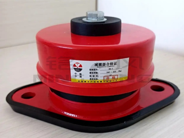
7. Accessories: vibration reduction pedestal, soft connection, inlet regulating door/air valve, muffler, temperature and vibration sensor, etc., configured according to system requirements.
3、 Common classification methods
1. Classified by blade form
Backward/backward curved blades: The direction of blade bending is opposite to the direction of rotation. High efficiency, usually up to 80% to 90%, with a power curve that is not easily overloaded and low noise, making it the preferred energy-saving universal model. Represented by 4-72 and G4-73 types of backward/wing shaped impellers, suitable for factory ventilation, air conditioning, dust removal, boiler induced draft, etc.
Forward/forward curved multi wing blades: The blades are short and numerous, with high wind pressure and compact size at the same size and speed. However, the efficiency is usually low, about 65% to 75%, and the motor is prone to overload when the resistance is low. Mostly used for air conditioning units, cabinet fans, and space limited air supply and exhaust.
Radial/straight blade: The blades are arranged along the radial direction, with a sturdy structure, wear resistance, resistance to clogging, and moderate efficiency. Suitable for dusty, particulate, and abrasive gases, such as woodworking, casting, grain, abrasives, and some kiln fumes.
2. Classified by full pressure level
In engineering, it is often divided according to total pressure, but there are slight differences in the boundaries of different standards:
Low pressure centrifugal fan: total pressure approximately ≤ 1000Pa (some old data use ≤ 980Pa). High air volume and low pressure, suitable for workshop ventilation, air conditioning supply, and ordinary exhaust.
Medium pressure centrifugal fan: The total pressure is about 1000-3000Pa (some data shows 980-2940Pa). Balancing air volume and pressure, used for dust removal, boiler induced draft, exhaust gas treatment, and medium-sized pipeline networks.
High pressure centrifugal fan: total pressure>3000Pa, commonly up to several thousand Pa, and special single/multi-stage can reach even higher. Used for pneumatic conveying, high-pressure spraying, long pipelines, furnace blowing, etc. Represented by categories 9-19 and 9-26.
3. Divided by intake and structure
Single suction: Gas enters the impeller from one side, and small and medium air volumes are common.
Double suction: Gas enters from both sides, with high air volume and balanced axial force, commonly used in large ventilation/air conditioning systems.
Single stage/multi-stage: one impeller per stage; Multi stage series connection of multiple impellers for pressure boosting, belonging to the category of high pressure or blower.
4. Classified by purpose and medium
General ventilation: delivering clean room temperature air.
Dust removal fan: wear-resistant and anti blocking.
Boiler air blowing/induced draft: G series air blowing, Y series induced draft, the induced draft should be temperature resistant, wear-resistant, and dust-proof.
Explosion proof fan: flammable and explosive gas, equipped with explosion-proof motor and spark free structure.
Anti corrosion fan: made of materials such as stainless steel, fiberglass, PP, etc.
High temperature fan: made of heat-resistant steel, cooling bearings, and insulated casing, used for kilns, sintering, and hot air circulation.
4、 Key performance parameters
The selection and use mainly depend on the following quantities:
1. Airflow Q: Unit time air supply, commonly used in m ³/h or m ³/s. It depends on the number of air changes, process exhaust volume, and the amount of air required for combustion.
2. Full pressure Pt: Import and export full pressure difference, Pa or kPa. Used to overcome resistance along the pipeline, local resistance, equipment resistance, and necessary dynamic pressure. The resistance of the pipeline network roughly increases with the square of the flow rate, that is, P ∝ Q ².
3. Static pressure Pst: Subtract dynamic pressure from total pressure. In actual pipeline selection, more attention is often paid to whether static pressure can overcome system resistance.
4. Efficiency η: the ratio of effective gas power to shaft power. The high-efficiency zone of the backward impeller can reach over 80%, while the forward multi wing is usually 65% to 75%. Efficiency affects electricity bills and operating costs.
5. Speed n: r/min. Similarity law approximation: Q ∝ n, Pt ∝ n ², axis power ∝ n ³. Variable frequency speed regulation utilizes this relationship to save energy, but attention should also be paid to bearings, noise, and critical speed.
6. Shaft power and motor power: Shaft power is calculated based on air volume, total pressure, and efficiency; The motor power should be multiplied by the safety factor. The general margin can refer to the shaft power of 1.05-1.2, depending on the load characteristics, starting method, and manufacturer's sample.
7. Noise and vibration: Noise is related to the impeller profile, speed, and flow deviation; Vibration is related to dynamic balance, alignment, bearings, and foundations. High end units will be marked with dB (A) and vibration speed in mm/s.
8. Medium conditions: temperature, density, dust concentration, humidity, corrosiveness, and whether it is explosive. Changes in air density will affect total pressure and power, and conversion is required for high temperature, low density, or high altitude.
5、 Selection ideas (practical engineering)
1. Calculate the air volume first: determined by multiplying the room volume by the number of air changes, or by the process exhaust volume, combustion air volume, and dust removal air volume. Industrial workshop ventilation can refer to 8-12 times/h, and kitchen exhaust can reach 25-30 times/h, depending on the pollution source and regulations.
2. Calculate the total pressure of the system again: resistance along the way+local resistance of bends/valves/reducers+resistance of filters/heat exchangers/dust collectors+necessary outlet dynamic pressure. Preliminarily, a full pressure of 1.10-1.15 and an air volume of 1.05-1.10 can be left with a margin, but it should not be too large, otherwise it will be inefficient and high consumption.
3. Pressure rating: Low pressure universal type is preferred for pressures ≤ 1000Pa; 1000-3000Pa selected pressure; 3000Pa high pressure/dedicated series.
4. Choose blade form: pursue high efficiency and energy saving, and choose backward direction for long-term operation; Small space, high wind pressure requirements, and stable resistance can be selected with forward multi wing options; Choose radial or specialized wear-resistant impellers for dusty wear.
5. Special requirements for the medium: wear-resistant lining plate and easy dust removal for dust content; Stainless steel/fiberglass for corrosion; High temperature heat-resistant steel+cooling bearings; Explosion proof electrical and anti-static structures.
6. Matching motor and regulation: Direct connection/constant speed can be used for fixed working conditions; Prioritize frequency conversion when changing loads. The throttling of the air valve is simple but lacks energy efficiency, while variable frequency regulation is more energy-efficient.
7. Check the performance curve working point: Draw the fan P-Q curve and the pipe network resistance curve together, and the intersection point is the working point. Try to fall within ± 10% to 20% near the highest efficiency point, avoiding the left branch of the hump and unstable areas; Attention should be paid to low resistance overload for the forward fan, and surge/low flow abnormality for the backward fan.
Common model intuition: 4-72 categories are commonly used for backward universal, low medium pressure, and ventilated air conditioning; Classes 4-79/4-68 are similar to general; Class 9-19/9-26 High pressure small, medium, and large flow, blower/induced draft/pneumatic conveying; Y4-73/G4-73 boiler induced draft and medium high pressure temperature resistance; HTFC cabinet type fire/air conditioning supply and exhaust.
6、 Typical application scenarios
Ventilation and air exchange in industrial workshops: for welding smoke, heat treatment, and assembly workshops, exhaust air is supplied to the medium and low pressure fans through pipelines after use.
Central air conditioning and building return air: forward multi wing or backward cabinet fans, emphasizing low noise and stable voltage.
Dust removal system: pulse dust collector, cyclone dust collector matching, medium pressure backward or radial wear-resistant impeller, processing dust containing gas.
Boiler/kiln air blowing and induced draft: air blowing for oxygen supply, induced draft for extracting high-temperature flue gas; The induced draft fan should be temperature resistant, wear-resistant, and dust-proof.
Pneumatic conveying: cement, fly ash, grain, plastic particles, high-pressure low flow or specific concentrated phase systems, commonly seen in 9-19/9-26 and multi-stage machines.
Chemical/anti-corrosion exhaust: FRP, PP, 316L stainless steel for acid mist and solvent vapor.
Fire smoke exhaust: A dedicated high-temperature resistant smoke exhaust fan that undergoes temperature resistance tests such as continuous operation at 280 ℃ according to building fire protection requirements, often paired with cabinet units.
Other: drying furnace hot air circulation, wastewater treatment aeration (Roots is more common, but some medium and high pressure centrifugation can also be used), printing coating line exhaust, laboratory exhaust cabinet.
7、 Key points for installation, operation, and maintenance
Installation: The foundation should have sufficient strength and rigidity, and the anchor bolts should be tightened; Make a vibration reduction pedestal for the large machine, add soft connections to the inlet and outlet ducts, and ensure that the pipes do not press the weight onto the casing. The requirements for direct alignment are high, and the belt conveyor checks the parallelism and tension of the wheel system; The concentricity of the coupling transmission should be calibrated. Before starting, manually turn the wheel, jog to confirm the steering, and check the status of the air inlet protective net, regulating door, and valve.
Operation monitoring: Focus on whether the air volume and pressure reach the design value, whether the motor current exceeds the limit, bearing temperature, vibration, and noise.
The temperature monitoring of rolling bearings generally does not exceed the manufacturer's specifications, and many projects use a reference temperature of no more than 75-80 ℃; Sliding/oil lubrication is managed according to oil level and cooling conditions. If severe vibration, abnormal friction sound, rapid temperature rise of bearings, and motor overload are found, the machine should be stopped for troubleshooting and not forced to run.
Daily maintenance: Regularly clean the impeller of accumulated dust, sticky dust, and oil stains: Dust accumulation can disrupt dynamic balance and cause vibration. In dusty environments, it can be shortened to once a month, while in ordinary environments it can be shortened to once every 1-3 months.
Bearing lubrication: Rolling bearings should be lubricated with lithium grease periodically, and the amount of oil should not be too much; Oil lubrication check the oil level, oil quality, and cooling water circuit. Sliding bearings are managed according to the clearance between the oil film and the bearing shell.
Fastener inspection: Regularly tighten the foundation, casing joint, impeller rivets/bolts, and coupling bolts.
Transmission components: Check the tension and wear of the belt conveyor, check the alignment of the coupling and the elastic body.
Long term shutdown: Regularly rotate the rotor to prevent rust and corrosion; Ensure dust and moisture prevention, and regularly inspect the insulation of the motor.
Common fault quick diagnosis: insufficient air volume/pressure: pipeline leakage, filter or impeller blockage, small air valve opening, reverse steering, belt slippage, low speed, low system resistance. High vibration: impeller dust accumulation/wear imbalance, dynamic balance failure, bearing damage, loose foundation, poor alignment, and entering surge. Bearing overheating: poor lubrication/excessive/insufficient oil, poor alignment, insufficient cooling water, bearing damage. Motor overcurrent: The system resistance is lower than the design, resulting in high flow overload of the forward fan, excessive medium density, low voltage, and mechanical jamming. Abnormal noise: impeller collision with shell, foreign objects entering, bearing damage, airflow pulsation/surge.
You can also contact us for more models and support customization

You only need one phone call
Leave the rest to us

The sales team will have a detailed discussion with you
Tell us your needs

Engineers based on your requirements
Provide a reasonable solution for the demand

We will do it within a reasonable time frame
Complete with quality and quantity assurance

Installation team on-site installation
Debugging until stable production

Any problems in the later stage are welcome
Contact the after-sales engineer
You can also contact us for more models and support customization
You only need one phone call. Leave the rest to us
The sales team will have a detailed discussion with you and tell us your needs
Engineers provide reasonable solutions based on your needs
We will complete it with high quality and quantity within a reasonable time
Installation team on-site installation, debugging until stable production
If there are any problems in the later stage, you can contact the after-sales engineer
 13806436798
Mobile